


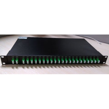

100g Athermal AWG / 41CH 100g Módulo Aawg / 100g Aawg
Informação básica
Modelo: 41CH 100G AAWG DWDM
Descrição do produto
C20 ~ C60 Tamanho: 19 polegadas, Iu Fibra: Fibra única Tipo da fibra: G652D, G657A Especificação: RoHS, ISO9001 Código do HS: 851762220 Tipo: DWDM Mux / Demux Certificação: CE, ISO, RoHS Potência: Athermal Espaçamento: 100g, 200g Conector: LC, Sc, E2000 Funtion adicional: Monitor Contagem de canais: 4,8,16,18,20,32,40,48CH Transporte Pacote : Em caixas Origem: China Athermal AWG (AAWG) têm desempenho equivalente ao AWG térmico padrão (TAWG), mas não requerem energia elétrica para estabilização. Eles podem ser usados como substituto direto para filtros de filme fino (tipo de filtro módulo DWDM) para casos em que não há energia disponível, também adequado para aplicações ao ar livre de mais de -30 a +70 graus em redes de acesso. Nosso Athermal AWG (AAWG) fornece excelente desempenho óptico, alta confiabilidade, facilidade de manipulação de fibra e solução de economia de energia em um pacote compacto. Diferentes fibras de entrada e saída, tais como fibras SM, fibras MM e fibras PM podem ser selecionadas para atender a diferentes aplicações. Podemos também oferecer pacotes de produtos diferentes, inluding caixa de metal especial e 19 "1U rackmount.
Os componentes planares DWDM (Thermal / Athermal AWG) são totalmente qualificados de acordo com os requisitos de garantia de confiabilidade da Telcordia para componentes de fibra ótica e optoeletrônicos (GR-1221-CORE / UNC, Requisitos Genéricos de Garantia de Confiabilidade para Componentes de Ramificação de Fibra Óptica e Telcordia TR-NWT-000468, Práticas de Garantia de Confiabilidade para Dispositivos Opto-Eletrônicos).
Especificação óptica (Gaussian Athermal AWG)
IL Representa o pior caso em uma janela de +/- 0.01nm em torno do comprimento de onda ITU;
PDL foi medido em polarização média sobre uma janela de +/- 0.01nm em torno do comprimento de onda ITU.
Informações sobre pedidos
Os componentes planares DWDM (Thermal / Athermal AWG) são totalmente qualificados de acordo com os requisitos de garantia de confiabilidade da Telcordia para componentes de fibra ótica e optoeletrônicos (GR-1221-CORE / UNC, Requisitos Genéricos de Garantia de Confiabilidade para Componentes de Ramificação de Fibra Óptica e Telcordia TR-NWT-000468, Práticas de Garantia de Confiabilidade para Dispositivos Opto-Eletrônicos).
Especificação óptica (Gaussian Athermal AWG)
| Parameters | Condition | Specs | Units | ||
| Min | Typ | Max | |||
| Number of Channels | 41 | ||||
| Number Channel Spacing | 100GHz | 100 | GHz | ||
| Cha. Center Wavelength | ITU frequency. | C -band | nm | ||
| Clear Channel Passband | ±12.5 | GHz | |||
| Wavelength Stability | Maximum range of the wavelength error of all channels and temperatures in average polarization. | ±0.05 | nm | ||
| -1 dB Channel Bandwidth | Clear channel bandwidth defined by passband shape. For each channel | 0.24 | nm | ||
| -3 dB Channel Bandwidth | Clear channel bandwidth defined by passband shape. For each channel | 0.43 | nm | ||
| Optical Insertion Loss at ITU grid | Defined as the minimum transmission at ITU wavelength for all channels. For each channel, at all temperatures and polarizations. | 4.5 | 6.0 | dB | |
| Adjacent Channel Isolation | Insertion loss difference from the mean transmission at the ITU grid wavelength to the highest power, all polarizations, within the ITU band of the adjacent channels. | 25 | dB | ||
| Non-Adjacent, Channel Isolation | Insertion loss difference from the mean transmission at the ITU grid wavelength to the highest power, all polarizations, within the ITU band of the nonadjacent channels. | 29 | dB | ||
| Total Channel Isolation | Total cumulative insertion loss difference from the mean transmission at the ITU grid wavelength to the highest power, all polarizations, within the ITU band of all other channels, including adjacent channels. | 22 | dB | ||
| Insertion Loss Uniformity | Maximum range of the insertion loss variation within ITU across all channels, polarizations and temperatures. | 1.5 | dB | ||
| Directivity(Mux Only) | Ratio of reflected power out of any channel(other than channel n)to power in from the input channel n | 40 | dB | ||
| Insertion Loss Ripple | Any maxima and any minima of optical loss across ITU band, excluding boundary points, for each channel at each port | 1.2 | dB | ||
| Optical Return loss | Input & output ports | 40 | dB | ||
| PDL/Polarization Dependent Loss in Clear Channel Band | Worst-case value measured in ITU band | 0.3 | 0.5 | dB | |
| Polarization Mode Dispersion | 0.5 | ps | |||
| Maximum Optical Power | 23 | dBm | |||
| MUX/DEMUX input/ output Monitoring range |
-35 | +23 | dBm | ||
PDL foi medido em polarização média sobre uma janela de +/- 0.01nm em torno do comprimento de onda ITU.
Informações sobre pedidos
| AWG | X | XX | X | XXX | X | X | X | XX |
| Band | Number of Channels | Spacing | 1st Channel | Filter Shape | Package | Fiber Length | In/Out Connector | |
| C=C-Band L=L-Band D=C+L-Band X=Special |
16=16-CH 32=32-CH 40=40-CH 48=48-CH XX=Special |
1=100G 2=200G 5=50G X=Special |
C60=C60 H59=H59 C59=C59 H58=H58 XXX=special |
G=Gaussian B=Broad Gaussiar F=Flat Top |
M=Module R=Rack X=Special |
1=0.5m 2=1m 3=1.5m 4=2m 5=2.5m 6=3m S=Specify |
0=None 1=FC/APC 2=FC/PC 3=SC/APC 4=SC/PC 5=LC/APC 6=LC/PC 7=ST/UPC S=Specify |
Grupo de Produto : Outras
outros produtos

produtos quentes
UTP Cat5e 24 portas systimax Patch PanelPlaca frontal de porta dupla AMPMódulos de telefone RJ11Conector RJ45 FTPJack Keystone UTP Cat5E / Cat62015 Chegada nova tipo armário de servidor de rede tipoCabo coaxial RG58 / RG59 / RG6 / RG11 75ohm Aplicar a CCTV / CATV com CE ROHS PadrãoCabo de comunicação de fibra óptica GYXTWCabo de ligação Cat5e UTP / FTP / SFTPSC Adaptador de fibra ópticaComutadores CISCO 2918Módulo de distribuição de 10 paresSplicer óptico da fusão / máquina de emendaConversor de mídia óptica de modo único 10 / 100MFábrica Atacado melhor preço cabo de comunicação 5/10/20/25/50/100/200 Pares HYAT Cabo de telefoneAlta qualidade fibra óptica splice box melhor preço